Medical devices
search
news
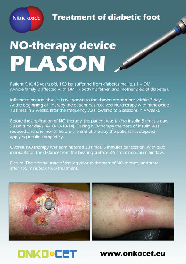
The PDF with the short report with pictures from the therapy of a diabetic foot can be viewed or downloaded here.
The pictures from the treatment of unhealing wounds an be found here:
http://www.onkocet.eu/en/produkty-detail/220/1/
The pictures from the treatment of unhealing wounds an be found here:
http://www.onkocet.eu/en/produkty-detail/293/1/

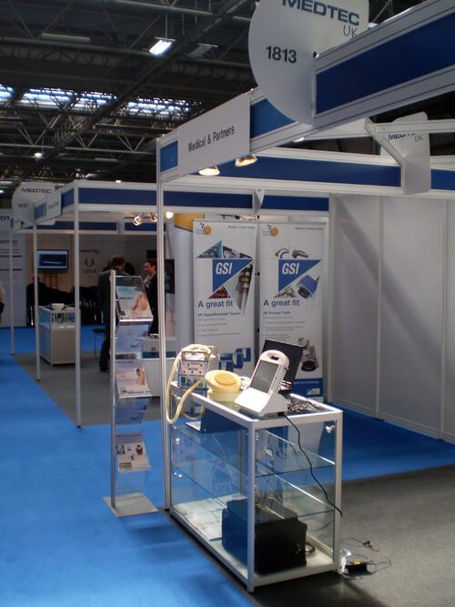
ONKOCET Ltd. has exhibited the devices from its portfolio on the MEDTEC UK exhibition in Birmingham, April 2011 through our partner Medical & Partners.
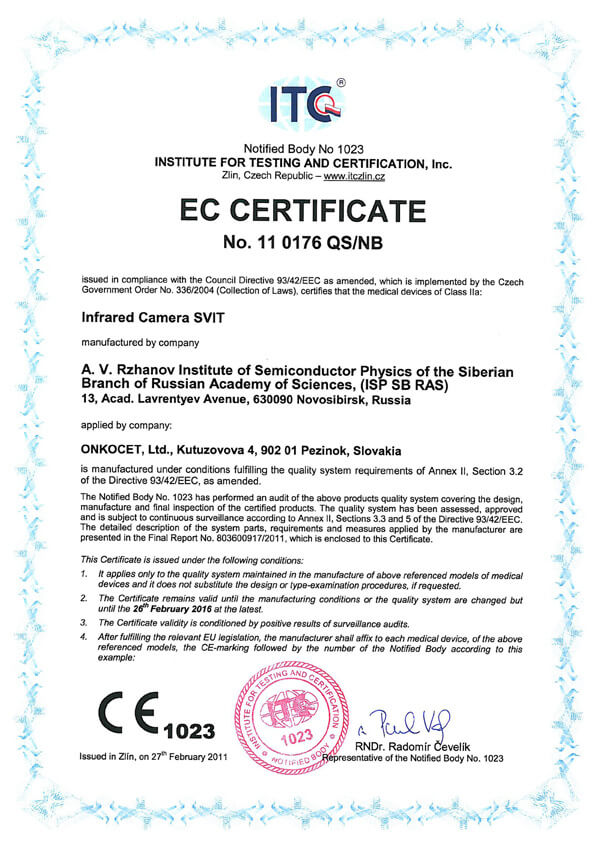 The ONKOCET company has successfully reached the certification of yet another medical device, Infrared Camera SVIT. The Certificate can be found here. The videos from the device operation can be found here.
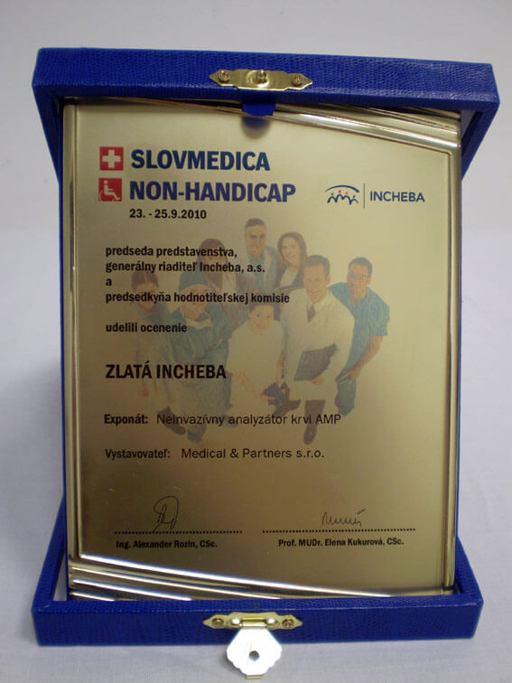 Our device, the non-invasive blood analyzer AMP has won the Golden Incheba prize at a medical exhibition SLOVMEDICA - NON-HANDICAP 2010. A big thank you goes to the organizers of the exhibition for acknowledging the quality of our device and to the exhibitor, the Medical & Partners company, for introduction of the AMP device to the medical public again.
We are pleased to inform our business partners, that our company has succesfully finished the certification process of Concor Soft Contact Lenses.
 You can find the certificate here.
More information on Concor Soft Contact Lenses go to section Medical preparations/Concor soft contact lenses, or follow this link.
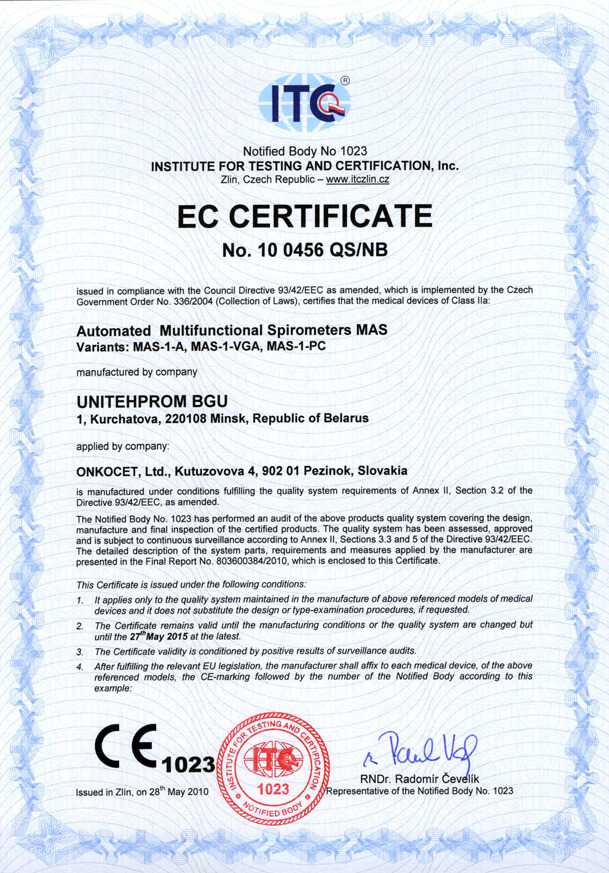 Our company has finished the certification process for another medical device, computerized spirometer MAS-1K with oximeter. You can find the device certificate here.
.jpg) Since May 2010 there is a new version of AMP device available.
Since May 2010 there is a new version of AMP device available.Follow this link if you want to see the pictures and specifications of the device.
http://www.onkocet.eu/en/produkty-detail/293/1/
 Dear partners,
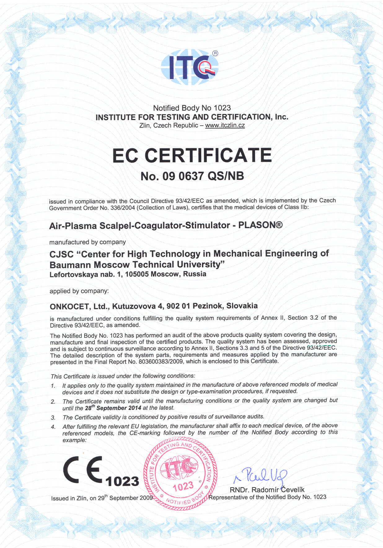
 In October 2009 we have received CE certificate for another device from our portfolio, NO therapeutical device PLASON. You can find more information about this revolutionary device, used for healing of unhealing wounds, diabetic foot, or for cosmetical purposes, at our webpage, section "Medical devices" -> PLASON-NO Therapy.
.gif)
Best regards
Team of ONKOCET Ltd. company
System Composition
System Composition
SGS-I is composed of Cobalt-60 Radiation Sources, Radiation Unit, Source Storage, 3-Way Treatment Bed, Localization Devices, Electrical Control System, Treatment Planning System (TPS), etc.
4.1 Mainframe
Radiation Sources, Radiation Unit, Source Storage, 3-Way Treatment Bed, External Decorative Cover, and Mainframe Base.
(1) SGS-I mainframe (see Figure 1.5)
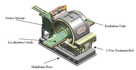
Figure 1.5 SGS-I Mainframe
(2) Cobalt-60 radiation source jacket (see Figure 1.6)
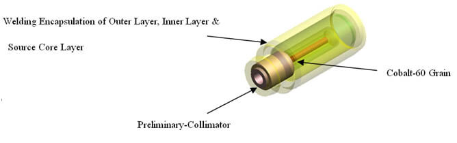
Figure 1.6 Radiation Source Jacket
(3) Distribution of Radiation Source Sector-focused. (see Figure 1.7)
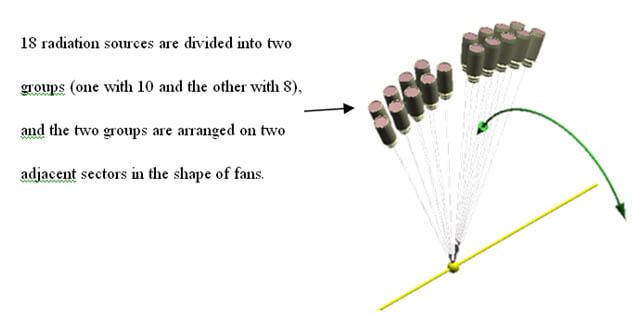
Figure 1.7 Distribution of Radiation Source Sector-Focused
(4) Radiation Unit (see Figure 1.8)
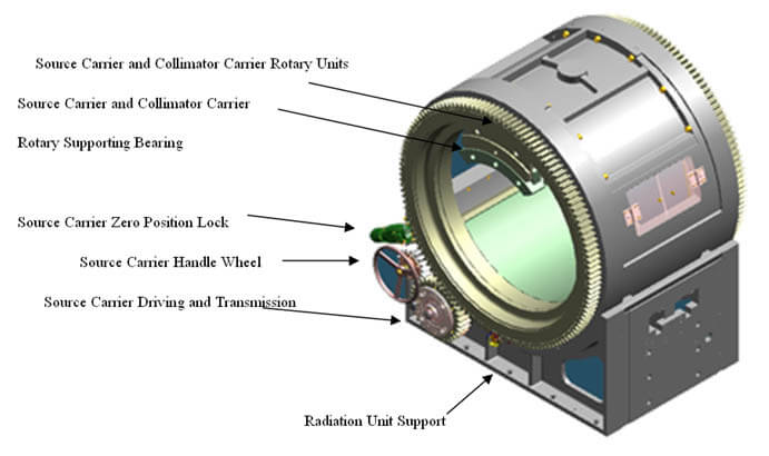
Figure 1.8 Radiation Unit
(5) Source Box & Radiation Source Containment Shell Assembling (see Figure 1.9)
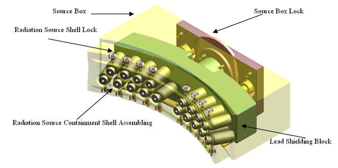
Figure 1.9 Source Box & Radiation Source Containment Shell Assembling
(6) Structure of Source Storage (see Figure 1.10)
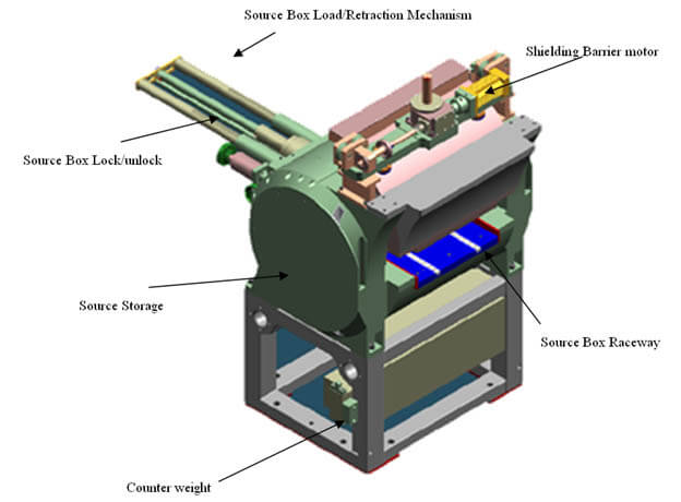
Figure 1.10 Structure of Source Storage
7) Structure of 3-Way Treatment Bed & Collimator Storeroom (see Figure 1.11)
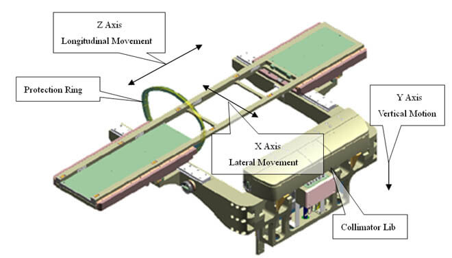
Figure 1.11 Structure of 3-Way Treatment Bed
4.2 Control System
The control system of SGS-I is in charge of the auto-control of SGS mainframe’s moving axes. It can systematically perform the treatment based on the TPS planning aically. The control system can also monitor the operation of machine and safety linkage, which insures that the equipment can be operated safely. In addition, the control system can process failure prompting/directing, save the necessary data, and retrieve the interrupted treatment.
The control system of SGS-I is composed of control computer, 8-axis motion controller, servomotors, stepping motors and drivers, one moment motor, two independent timers, PPC, zero position switch and limit switch, power, etc. (see Figure 1.12)
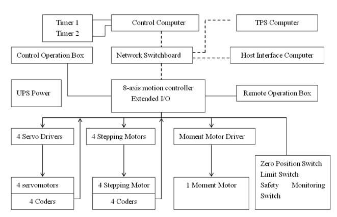
Figure 1.12 Block Diagram of the Control System
The power is supplied by Electric Supply and online UPS. When there is Electric Supply failure, UPS will be able to make the equipment run properly for more than 30 minutes to make sure that the treatment will not be broken off when power is suddenly removed. The voltage of the UPS is 230 VAC, and the power is no less than 5kVA, 0.5h.
The actuators of the source carrier and collimator carrier include the drivers, motors, incremental encoders, etc. The position detection and localization among source carrier and collimator carrier is undertaken by the incremental encoders and proximity switches. The state of open/close of the radiation sources is displayed by the status indicator lamp. The rotating speed and rotating range which is used by the upper control computer to control the 6K8 movement controller is determined by the TPS planning. During the treatment, the maximum rotating speed of source carrier and collimator carrier is 1.16rpm.
The x, z movement of the treatment bed is achieved by the decelerated motion device driven by the stepping motor. The y movement is achieved by the decelerated motion device driven by servo motor. The position of all the movements is fed back to the 6K8 controller through the encoders, which ensure the positioning accuracy of the treatment bed. Moreover, the three axes on the treatment bed have zero position switches and positive-negative motion limit switches, which can ensure the safety operation of the treatment bed and the determination of the axes’ zero position. The shielding barrier of the source storage is driven by a servo motor, while the pushing bar and the source lock are driven by the stepping motors. The position inspection is achieved by proximity switches.
The control of radiation dosage is composed of two independent timers. These two timers use redundancy association and each can terminate the radiation independently. When SGS-I is started to radiate, one timer is timing ascendingly and the other is timing descendingly. Timers will be displayed in the Remaining Time and Elapsed Time on the control panel. The timers are initialized by the upper control computer. When any one of the timers goes out of order (the value of the two timers has more than five seconds difference or one of the timers powers down), the treatment will be terminated with an alarm and the failure will be displayed on the upper control computer. When the radiation is stopped accidentally, the value of the current timers will be saved individually on the timers as well as the upper control computer for later examination.
SGS-I Safety Linkage
SGS-I is equipped with safety linkage to ensure the safety of equipment and people. Understanding and using these safety linkage properly is the precondition of the treatment. (see Table 1.1)
Table1.1 SGS-I Safety Linkage List
| Put in working order | Before treatment | Under treatment |
Emergency Stop Button | Operative | Operative | Operative |
Protect Ring | Operative | Operative | Operative |
Power Key | Operative | Operative | Operative |
Treatment Room Door | Inoperative | Operative | Operative |
Localization Couch Positioned | Inoperative | Operative | Operative |
Timer Linkage | Inoperative | Inoperative | Operative |
Localization Deviation Linkage | Inoperative | Inoperative | Operative |
(1) Emergency Stop Button & Protect Ring
· SGS-I has two emergency stop buttons. One is on the control panel, the other is beside the machine.
· SGS-I has one protect ring which is used to protect the human body against being hurt by the machine mechanically.
· No matter when the emergency stop buttons or protect ring operate, the power will be shut off.
(2) Conditions of safety linkage when put in working order
· SGS-I only can be started up by using keys.
· There are emergency stop buttons on the control panel and beside the machine. Only when all the emergency stop buttons are under disarm state, can SGS-I be put in working order. That is to say that SGS-I is put in a state of waiting treatment. When SGS-I is in the state of waiting treatment, the OK indicator light will be shown that the equipment is ready for treatment.
(3) Conditions of safety linkage prior to treatment
The following conditions must be satisfied prior to treatment.
· Localization couch must be positioned on the treatment bed properly;
· The treatment room door must be closed.
· The treatment time must be re-determined on the control computer, otherwise the radiation cannot be processed.
(4) Conditions of safety linkage under treatment
· Treatment room door must be closed, otherwise the control panel will alarm and the beams will be off aically;
· The localization couch must be fixed tightly on the treatment bed, otherwise the control panel will alarm and the beams will be off aically;
· When any of the two timers accrues failure of power supply, the radiation will be terminated;
· When the value of the two timers have more than 5s difference, the radiation will be terminated;
· If the synchronous tracking deviation between collimator carrier and source carrier is more than 1 degree, the radiation will be terminated.
(5) The safety state indication of the treatment room
When Cobalt-60 sources are in the source storage and the source storage is closed, the state of treatment room is under safe condition. There are two independent verification system used to indicate the state of the treatment room.
· Indicator light at the door of the treatment room: It is controlled by a set of machinery linkage. The green light indicates safe state, while the red light indicates that cobalt-60 is not in the source storage;
· Indicator light in the control room: It is controlled by the radiation dosimetric system. The green light indicates safe state, while the red light indicates that cobalt-60 is not in the source storage.
4.3 Positioning Device
Stereo-Positioning Device is one of the important components of SGS-I. Its functionality is to set up a 3-D coordinate system between patients and the equipment, so that the position of lesion can be determined. In the process of diagnosis positioning, the stereo-positioning device is used to accurately determine the target’s size and position in the said coordinate system. In the process of treatment positioning, the lesion is to be repositioned to its initial position and thus the accurate multiple repositioning can be realized.
Components of Stereo-Positioning Device
The SGS-I stereo-positioning device comprises Head Positioning Device and Body Positioning Device:
A. Head Positioning Device is composed of Primary High Precision Head Positioning Device and Multi Repetitive Head Positioning Device:
· Primary High Precision Head Positioning Device is mainly composed of stereo localization head frame, fixed head pin, MRI/CT marker frame, MRI/CT adapter rack, etc.
· Multi Repetitive Head Positioning Device includes CT, repetitive Positioning Devices, mask, etc.
B. Body Positioning Device can be used to position the patient repeatedly. Human body fixation has two types: vacuum cushion and mask.
Body Positioning Device includes localization couch, repositioning devices, vacuum cushion (or mask), armrest, etc. Localization couch is the basic component of head localization and body localization. (see Figure 1.13) 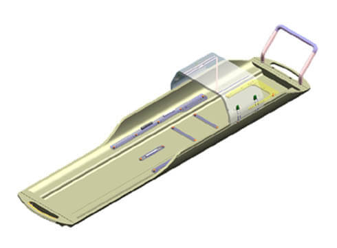
Figure 1.13 Localization Couch
4.4 Treatment Planning System (TPS)
TPS accomplishes the radiation treatment planning. TPS enables radiation doctors, physicists to do dose planning and optimization for tumor or other diseases’ treatment simulation.
TPS plays very important role in clinical treatment. It is a kind of computer auxiliary tools that can be used to help radiation doctors and medical physicists to do dose planning. Through the acquisition and processing of patients’ medical image information, the users can obtain the geometry description of position and volume of body surface, target and VOI accurately. Users can determine the target and arrange the focus through interactive manipulation. The dose calculation will be finished systematically, and the dose distribution of the lesion and the surrounding normal tissue will be displayed in isodose line or isodose surface. Furthermore, users can completely evaluate the treatment plan with Dose Volume Histogram. With the prescription determined, the position of target, the radiation, and the treatment time could be exported. All the treatment parameter will be transmitted to the SGS-I via network.
4.4.1 TPS Hardware
a) Image Acquisition Device
· DICOM network transmission interface (provided by the hospital).
· Transmittable Film Scanner gray level> 256(if no DICOM).
b) Workstation
· Windows workstation > 1GHzCPU-40GB SCSI HD-VX-1 Display Card (1280 x 1024 x 16 bits);
· 21” color display.
· CD burner driver, backup tape driver;
· Operating System: Windows 2000/XP.
c) Output Device
· Color printer.
d) LAN
The workstation is equipped with double network cards. One of them is connected to the SGS-I LAN, the other one is connected to CT/MRI scanner.
4.4.2 TPS Software
· Structure of TPS Software (see Figure 1.14)
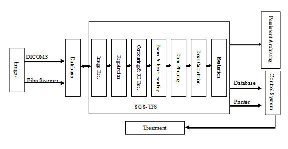
Figure1.14 Architecture of SGS-TPS
· General introduction of the TPS software
SGS-TPS is a 3D treatment planning system which is used to help physicians or medical physicists to do treatment planning based on the patients’ medical image information. The functions include:
(1) Machine Data Entry
Allowed to modify or reset the machine parameter under the control of certain safety level.
(2) Image Acquisition and Management
The image series could be input to SGS-TPS image database through DICOM interface or film scanner. DICOM interface is used in inputting CT/MRI/PET image series which are DICOM compatible. Film scanner is used to input images of patients on the film.
(3) Image Reconstruction
TPS can do the other orthogonal image reconstruction based on the input transverse image series, and three orthogonal anatomical planes can be displayed (transverse, sagittal and coronal section) that goes through any point within the range of reconstruction.
(4) Contouring and 3D Reconstruction
Auto-contouring and manual contouring could be done to the external, target and VOI, based on which 3D reconstruction can be achieved with wireframe, transparent and solid. It is to illustrate the position of target, sensitive tissue and external surface in 3D space.
(5) Image Registration
SGS-TPS supports semi-auto registration and manual registration. The registration operation includes registration of head CT images, head MRI images and body CT images.
(6) Selection of Rotating Range
With the patients’ target position, sensitive volume position, appearance information of treatment bed cover and the size of metal stand determined, SGS-TPS can do collision detection aically and the available rotation range can be displayed.
(7) Dose Planning
SGS-TPS supports single focus, multi-foci and trajectory foci planning. The focus’ parameters (such as numbers, position of focus, collimator sizes, etc) can be set mutually as well as beam’s parameters (such as starting angle and ending angle).
(8) Dose Calculation
Narrow Beam algorithm is applied by SGS-TPS for dose calculation to determine the radiation time of each segmental arc according to the prescription and weighting.
(9) Plan Evaluation
SGS-TPS supports multiple plans and evaluation approaches, including DVH, isodose line in 2D images, isodose surface in 3D display, which will help the users to evaluate the treatment plan effectively. Multiple plans comparison through DVH can be performed by SGS-TPS.
(10) Prescription
Determine the actual radiation dose.
(11) TPS Export
Treatment plan, treatment report, DVH and treatment sheet can be printed or plotted, in which there are some important information like focus position, arc beam attributes, radiation time, etc. Treatment report includes patients’ name, planning time, planner, and physicians’ signature column. Evaluation images includes selectable dose volume histogram, isodose distribution of three anatomical plane, and 3D dose distribution (isodose surface, organ at risk).
(12) Patient Management
Manage the raw images, volumes and plan information of patients.